It may just be my new fitness routine, but I found this quite funny.
Found on http://physicshumor.blogspot.com/
I can’t read the signature on the lower right so I can’t give credit where its due.
Wednesday, August 28, 2013
Electrical Humor


Monday, August 26, 2013
Toggling Dots to Angles and Back Again
This is a follow up to the <<Swapping Entire Symbol Libraries Project Wide>> post. After switching all symbols from JIC to IEC, the next step could be switching wire connection dots to angle connections.


There is an existing to
After starting the command, window select the dots to be converted. Or type ALL and press enter. This selects the entire drawing and converts all connection dots at once. I noticed it only seems to select the dots that are currently on the screen even when typing ALL. So be sure to Zoom Extents first.
Editing this buttons macro to do all dots would be as easy as…
ZOOM E AETOGGLETEE ALL ^C
(note the space behind the ^C)
So moving from dots to angles is quite easy. How about angles back to dots? Not so easy, but I’ve found a script that does just that.
Download it <<here>> or make your own using the script below.

Remember a script can be run project wide from the Project Utilities dialog.
Saturday, August 24, 2013
2014 Content update for Rockwell Automation (Allen Bradley)
This update adds new AB content to the existing AutoCAD Electrical content databases.
http://usa.autodesk.com/adsk/servlet/ps/dl/item?siteID=123112&id=21972810&linkID=9240738
As with any update be sure to review the Readme to be sure its installed properly.
This link contains the additional content details.. AB-RA Content Details
Wednesday, August 14, 2013
Mirroring Components the Proper Way – AutoCAD Electrical
Once again I have a someone using AutoCAD commands inside of Electrical and their confused by the results. This time it was AutoCAD’s MIRROR command causing the problem. When using the AutoCAD MIRROR command, the wire connection attributes end up switching sides and future wires will attempt to enter the wrong side of the symbol.
Below the connector has been mirrored using the AutoCAD command and notice how the new red wire now pulls off of it. Its because the wire connection attributes have switched sides.

The wires know what direction to go based off of attribute name.
X1TERM0# wires come into the component from the right.
X2TERM0# wires come into the component from the top.
X4TERM0# wires come into the component from the left.
X8TERM0# wires come into the component from the bottom.
The answer is to simply use the correct AutoCAD Electrical command: Reverse/Flip Component

Thursday, August 8, 2013
Adding Cross Reference (XREF) Info To Footprints – AutoCAD Electrical
 Today I was asked how to pull cross reference info from the parent symbol into a footprint. This works great on child components. Simply add an XREF attribute to a child component (if its missing) and on placement it auto populates with the parents sheet and reference location. However add an XREF to a footprint and nothing happens to it.
 Out of the box, footprints do not pull this information even if the footprint contains an XREF attribute. However this information is available because multiple commands reference the footprints back to the parent symbol. None is more visible than the Surfer

In the surfer dialog above we can clearly see a reference between the parent, a child, and the footprint. So the question is, how do we go about getting this information info the footprint?
Below is a nifty utility wrote by Nate Holt back in 2009. (I tested it in 2014 and it still works great) It uses the same calls to the database that the Surfer users to capture this information and then writes it into an attribute named XREF on all the selected footprints.
Simple APPLOAD it and then type the command PANEL_CROSSREF
Add an XREF attribute Run the command Select the footprint Press enter…


Monday, August 5, 2013
Flattening 3D Models Into 2D Footprints – FLATSHOT
It seems many vendors are no longer offering 2D drawings of their components and are instead posting 3D models. This makes for a very large drawing and affects overall performance.


Now type in the command FLATSHOT.
Set the destination for the new 2D block. In this example I will simply insert it back on the same drawing. However a footprint could be exported directly to the Custom Footprint folder from here.
Next you configure the lines. Checking ‘Show’ under Obscured lines will add hidden lines to the footprint.
Press Create and verify the new 2D block is as desired.


I have seen a few other ways to do this type of thing but personally FLATSHOT is my favorite. Its simple yet has a number of options. And its already a part of the software.
Monday, July 8, 2013
Swapping Entire Symbol Libraries Project Wide
Having completing an entire project using JIS symbols, you are told the client would rather have JIC style symbols. Never fear ‘Swap/Update Block’ saves the day.

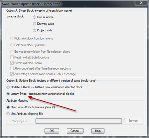 If you are planning on going project wide, I would recommend making a backup first.
Active drawing is better for testing your selection to verify results before going project wide. If your not happy with the results simply close the drawing and don’t save. Be sure to set the proper scale. Some library styles are in metric other are not.

Here is a before and after example after switching from JIS to JIC.


The tool in action…


 If you are planning on going project wide, I would recommend making a backup first.
Active drawing is better for testing your selection to verify results before going project wide. If your not happy with the results simply close the drawing and don’t save. Be sure to set the proper scale. Some library styles are in metric other are not.

Here is a before and after example after switching from JIS to JIC.


The tool in action…

Sunday, June 30, 2013
Surfing a Project Using Wild Cards – Fix_Me 2

Create a new symbol called fix_me and add it to the icon menu. Make sure to add fix_me- to the TAG1 attribute as the default prefix. Now it can be inserted like a normal symbol. The tag will take on fix_me- as a prefix and whatever the proper reference number should be. ex. fix_me-101
Now to surf project wide for any symbols starting with fix_me….
Start the Surfer from the Project tab.
The command is asking you to select something for the Surfer to tract. Instead press Enter.
From this dialog you can use many wild cards to search the entire project for components, catalog numbers, wire numbers, and item numbers.


Add fix_me* to the Component tag field and press OK. Project wide all components who’s TAG starts with fix_me are shown. From here I can surf to each one.
This gives a list of all components in one list. Something the ‘fix_me’ script does not. However users will need to remember to run this from time to time. Where as the ‘fix_me’ script runs every time the drawings is opened.
Just another option. I thought it was a cool idea. Thanks Jeff.
Running a LISP, or Command, on File Open - (Fix_Me)
You can set a LISP utility to run each time you open a drawing from the Project Manager. This is set in the wd.env file. Look for the line that starts with *WD_OPEN_DWG.
<<Link to my post about the wd.env file>>
“How do I mark a symbol/wire that has a problem, or missing information, and later quickly find it?” Last week this question came up again.
Below is some code that you can find inside of Electrical’s help as sample LISP code. Simply copy and paste it into a text file and save the file as Fix_Me.lsp. APPLOAD this file.
(defun c:fix_me ( / ss en ed xy)
; Look for any block insert on the drawing with a block name of "FIX_ME"
(setq ss (ssget "_X" '((-4 . "<AND")(0 . "INSERT")(2 . "FIX_ME")(-4 . "AND>"))))
(if (/= ss nil)
(progn ; one or more found. Zoom up on the first one found
(setq en (ssname ss 0)) ; entity name of first or only block
(setq ss nil) ; release the selection set
(setq ed (entget en))
(setq xy (cdr (assoc 10 ed))) ; block insertion point
(command "_.ZOOM" "_CENTER" xy 1.0)
(princ "\nThis needs attention!!!\n")
) )
(princ)
)
Typing ‘fix_me’ will now run the script which zooms in on the first block named fix_me that the script finds. So create a block named fix_me and give it attributes for notes as well as all symbol attributes. This fix_me symbol can then be used when a needed symbol is missing and the engineer is waiting on the CAD Admin to create it. Once the new symbol is finished the fix_me symbol can be swapped (Swap/Update Block) with the new one. Values in the attributes will carry across to the new symbol. It could also be placed off to the side of a symbol with missing catalog info, or anything else the engineer is unsure of at the time of placement.
So once the LISP file and block are created, why not run them each time a drawing is opened? This takes us back to the WD_OPEN_DWG line in the wd.env file. If your block and LISP files are both named fix_me replace the default *WD_OPEN_DWG line with this…
WD_OPEN_DWG,(if(not c:fix_me)(if(setq x(findfile "fix_me.lsp"))(load x)))(if c:fix_me (c:fix_me))
Pretty slick right.
Friday, June 28, 2013
Modifying Attributes In Existing Blocks – AutoCAD Electrical
Anyone modifying existing block attributes has run into the mysteries of how to update the existing blocks on the drawing. Reinserting the block doesn't update the attributes. I should be using Swap/Update block. However when testing I tend to keep the changes inside the test drawing using embedded blocks. Doing this means the existing occurrences of this updated block must have their attributes synchronized. 
The only problem I have with this method of updating existing blocks is having all attributes return to the blocks default layer. Today I learned when using the Swap/Update block all attributes are placed back on the proper Electrical layer. This is a great little discovery. Now I can continue editing the block within the drawing until I’m happy with it, then WBLOCK it back out to the library. Following that up with an Swap/Update puts existing blocks back in order.


Subscribe to:
Posts (Atom)