The Symbol Builder guides you in the making of symbols. Its very easy and quick to create your own “intelligent” symbols. In this post we will look at the basic workflow and some general guidelines used when building symbols.
Starting the Symbol Builder
The command is on both the Schematic and Panel tabs. There is no differences in how the command starts, or its options, between the two locations.
Select Symbol Objects and Attribute Template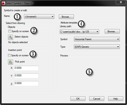
If the reference geometry is already in block form, it can be selected from the (1) embedded block list drop. If the block is external, it can be selected by pressing the Browse button. The block can also be simply selected using the (2) select objects button.
Any existing geometry, text, and attributes, not in block form, can be selected using the (2) select objects button as well. Nothing is required here since the entire block can be created inside the Block Editor environment.
Tip: Verify the symbols size will match up with the default wire connection spacing for the desired standard. If wire connection spacing is not consistent between symbols extra clean up will be required when swapping blocks.
Specify the insertion point using the (3) pick point button. This can be changed later but it will make working in the Block Editor easier if this is specified now.
Next we choose the proper attribute template (4) The path points is to the default symbol library NOT where you wish to save this block. The attribute blocks are saved there. Just make sure the proper standard is selected. The other two menus narrow down which attribute template will be used. They also aid in naming the block later. A later post will discuss attribute template blocks in more detail.
The preview area (5) should show a little view of the geometry that was selected. If a block was selected the attribute names will show instead of the actual values the attributes hold. Pressing OK opens the Block Editor
 The Block Editor
First a quick overview of the Symbol Builders Block Editor environment.
(1) The biggest thing on the Symbol Builder tab is the option to toggle the visibility of the (2) Symbol Builder Attribute Editor panel. Use the Done button once the symbol is complete.
The (2) Symbol Builder Attribute Editor panel is the heart of this little environment. It allows easy insertion of required attributes based on the previously selected attribute template as well as wire connection locations. We will discuss it in detail in the next section of this post.
There is really no reason for the (3) Project Manager. It could be closed and reopened from the Project tab after the symbol creation. The same can be done for the (4) Dynamic Block Authoring Palette. It is used in the creation of dynamic blocks and rarely used in AutoCAD Electrical. It can be toggled back on from the Block Editor tab.
The (5) graphic area is the blocks model space. If additional geometry, text, or attributes are needed, simply switch to the Home tab and add or modify as required. Pretty much anything that can be created in AutoCAD can be created here in the Block Editor environment.
Using the Symbol Builder Attribute Editor
When this palette first came out it had a lot of people really upset. I’m not sure why. From the start I felt this was about 1200 times better then the black box symbol builder dialog. 
Before we get into the attributes, I want to point out this button. This button opens a dialog that allows a new attribute template to be selected. It also allows a new insertion point to be selected but you will have that option later as well.
Attributes
Now onto attribute placement. This is really slick. Simply select the desired attribute and press the first little icon.  If the icons are
 too small for you, right click and all of the same options are available there as well. After choosing Insert, click to place the attribute in the graphics window. Another way to insert, is to select the desired attribute and then simply click and drag the attribute line into the graphics window. When the mouse button is released the attribute will be waiting for placement.
Note the second option is Convert Text  (third icon). This is a great command when converting existing
  AutoCAD blocks. Selecting text will carry the text formatting into the attribute keeping the same look. A side effect to this is the text value becomes the attributes default value. This can cause a problem if selecting text stating LT100. That will become the new default prefix for all tags when using this symbol. After all attributes are placed, review the attribute defaults before continuing to the next step.
To reuse existing attributes from an existing AutoCAD block, simply double click it and rename its TAG to match a desired attribute line. What do I mean by this? Note the image below already has an attribute for TAG called TAGNUMBER.


If I rename this original attribute to AutoCAD Electrical’s default TAG1, immediately the TAG1 attribute line is confirmed.


If a symbol has no text to convert and it’s the default size, all attributes can be placed at the same time. Select all of the attributes in the palette and then insert them as a group. The insertion will be based off of the attribute templates origin and where that attribute lives in the template. So zoom out a bit because some of the attributes may be slightly off screen when placing.


Some attribute templates will have some optional templates that can be placed as well. Remember this is AutoCAD. Place any extra attributes necessary. They can always be edited using the AutoCAD attribute editors and their values can also be used in reports later.
Wire Connections
 Wire connections consist of two attributes and could be placed manually. However this utility will place and name them properly for you. Click in the white space beside Left/None and a drop down arrow will appear. Click the arrow and all of the possible wire connections are available for selection. Choose one and then press the little icon
  above it to place a new connection in the graphics window. Remember to use OSNAP’s when placing these connections. (Shift+Right Click) The wires will end on the attributes insertion point not the geometry being selected.
If a series of connections is needed simply keep clicking. Wire connections will continue to be placed. Remember to switch connection types as needed or wires will not connect properly. 

If this symbol will always receive the same pin numbers, they can be called out here in the attribute default area.
Link Lines

Dash linked lines are setup pretty much the same as wire connections. Make sure to add all possible directions for the symbols needs.
In the example below, you can see the need for both sides of the connection in most symbols needing link lines. The exploded blocks on the right are copies of the linked selector switch on the left. The link line attributes are shown on the image on the right.


Close Block Editor: Saving the Symbol
Ok so that’s about it for the basics. How bout we turn this into a block and test it? From the Symbol Builder tab select Done.

Once again note the ability to set the base point. The insertion point should be set by now but if not this is the last chance.
Choose if this block should be (1) imbedded in this drawing only (block) or wrote to an external dwg (wblock). Then we move on to naming the block. The symbol prefix is already taken care of. Simply update the (2) unique identifier field and then click/tab out of the field. This will cause the bock and image name to update. If no icon image is needed, clear the check (3) for icon image.
The (4) file paths should be set by the wd.env file. Even so verify the paths are pointing to the proper locations.
Finally review the errors found by the block audit by pressing the (5) Details button.
After pressing OK you are given the option to insert the block after closing the block editor. The correct answer here is Yes. Verify that the wire connections work and attributes are in their proper location. If not, take the block right back into the Block Editor and fix the problem.


